Overview
Calculate the series resistor value for an LED using:
You need three values from your design:
- -> supply rail (GLV or logic voltage)
- -> LED forward voltage (datasheet)
- -> target forward current (datasheet; 1–5 mA is typical for SMD indicators)
Circuit description
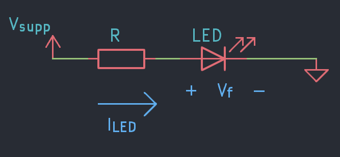
A single resistor R is placed in series between the supply rail and the LED anode. Current flows through R and the LED to ground. R drops the difference between and , setting the current through the LED.
Gotchas
The resistor drops the excess supply voltage, dissipating it as heat. At higher supply voltages this becomes significant - don’t assume a 0402 is fine.
For example, driving an LED from 12 V. Note a higher current for this example:
For this example, 95 mW exceeds the rating of a 0402 (62 mW) and sits right at the limit of a 0603 (100 mW). Use 0805 (125 mW rated) or larger for any 12V GLV-supplied indicator.