Overview
A low-side transistor relay driver is one of the most fundamental circuits in a Formula Student shutdown system. It allows driving a relay coil that may draw 30-200mA from a microcontroller GPIO, or logic circuit output that may only be capable of up to 5mA.
Circuit description
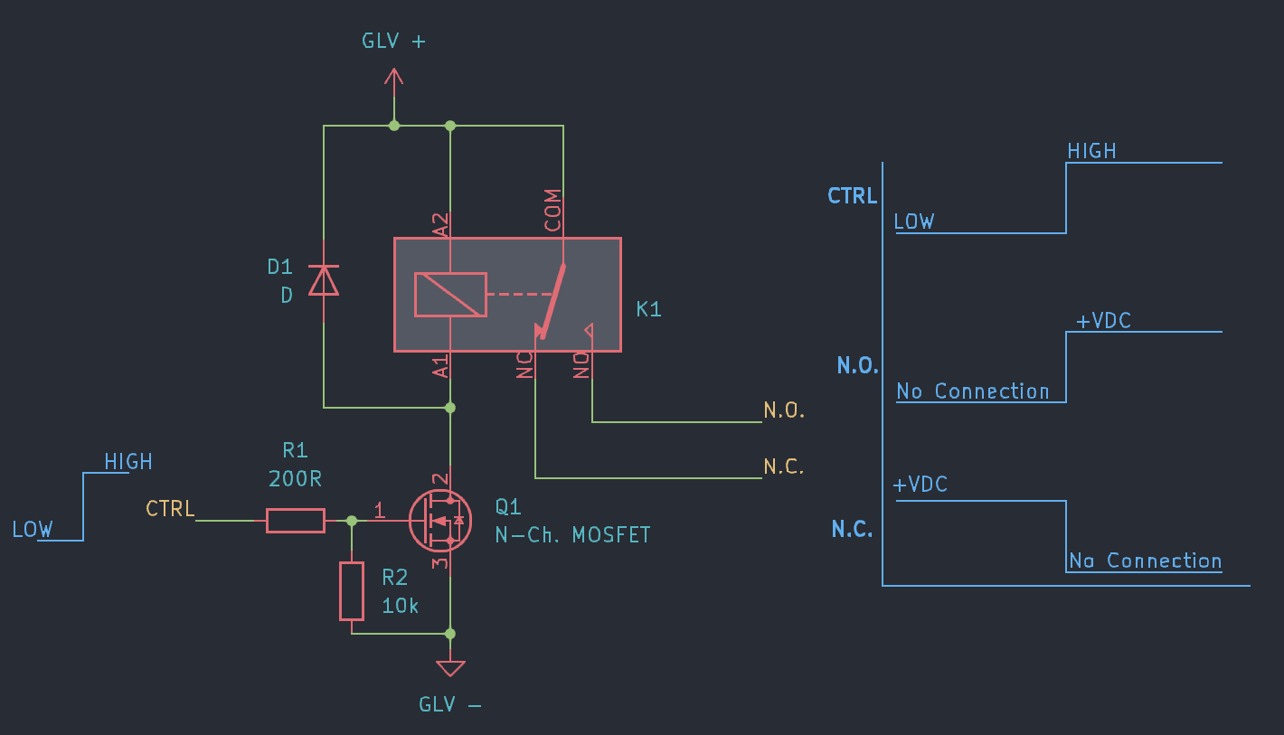
The microcontroller/logic circuit drives the gate of N-channel MOSFET Q1 through a gate resistor R1. The MOSFET turns ON, which allows current to flow through the relay coil. The relay coil is connected between the supply rail and the MOSFET drain. A flyback diode D1 is placed across the coil to suppress the inductive kick when the transistor turns off. Note the diode is oriented against the operating current flow in the coil.
Design notes
- Gate Resistor: Since MOSFET gates have capacitance, a gate resistor is commonly used to reduce current spikes when switching the gate on/off. For instance, when transitioning from low to high, the capacitive gate briefly looks like a short circuit which will pull a very high current from the control circuitry.
- Pull-Down Resistor: R2 is the ‘pull-down resistor’ and its function is to stabilise the gate voltage. If the upstream driver is a high-impedance circuit, the sensitive gate can trigger from inducted noise or RF signals. This pulldown resistor ensures the gate voltage remains low, by acting as a small load which dissipates these spurious signals.
- Flyback diode: Mandatory. Without it, the inductive spike can exceed 100 V and destroy the transistor or corrupt nearby logic.
- Transistor selection: Ensure the gate operates at your selected control-signal levels, and that the continuous drain current can handle the relay coil current. Common low-current parts are 2N7002, BSS138.
- Relay selection: Confirm coil voltage matches your GLV rail (typically 12 V or 24 V). Verify contact ratings exceed expected current of the downstream circuit eg. if this is a component in the shutdown circuit it should be able to handle the IRs inrush current.
Gotchas
- Ensure the MOSFET is oriented correctly, with the drain connecting to the coil, and the source connected to the negative supply. A useful visual mnemonic is that the body-diode in the MOSFET schematic symbol points against the current flow - similar to the flyback diode D1.
Rules relevance
EV.7.1–7.2 governs the Shutdown Circuit latching behaviour and the requirement that each node in the circuit can interrupt current flow. This driver is typically used to energise AIR contactors or the TSMS relay under shutdown circuit control.