We’ll cover:
- Why precharging is essential for protecting the IRs from enormous inrush currents during switching.
- Selecting an appropriate precharge resistor for an example system that meets chosen precharge characteristics.
- Voltage measurement and how it is used for detecting Precharge-Complete, or Precharge-Failure.
Why precharge?
Modern motor controllers contain large bulk capacitance on their HV bus, often 330-4000 µF. If the main Accumulator Isolation Relays (IRs) are closed with uncharged capacitors, the inrush current is limited only by the DC resistance of wiring, the relay contact resistance, and the ESR of the capacitors. This produces:
- Relay contact welding - the current spike can weld IR contacts closed, an unsafe and unacceptable failure mode.
- Voltage stress on capacitor ESR - high peak currents cause localised heating and reduced capacitor lifetime.
- Fuse nuisance tripping - the spike may exceed the fuse’s rating.
How it works
A proposed FSAE precharge topology uses a series resistor and a precharge relay in parallel with the positive IR.
- All upstream Shutdown Circuit conditions are met (BSPD, IMU etc.): the Shutdown Circuit delivers GLV power to the negative IR (IR-) and the Precharge circuit, which powers up.
- The precharge relay is closed, passing current from the accumulator into the Tractive System via the precharge resistor . The capacitor(s) in the motor driver(s) begin to charge, and the TS voltage rises, following a predictable RC curve.
- The Precharge Controller waits until the target TS voltage is reached, then, in sequence:
- Closes the positive IR (IR+)
- Opens the Precharge relay.

Resistor selection
Bottom Line: Select your precharge time to be as long as practicable to avoid pulsing high-power through your precharge resistor.
The time constant for precharge is .
should be kept to at least 1 second, to avoid pulsing high energy into the precharge resistor. A target precharge of 95% is achieveable in time :
Example calculation
- (example)
- Select target precharge time
- Choose , Peak current
- Power dissipation (worst case, full V across R): instantaneous.
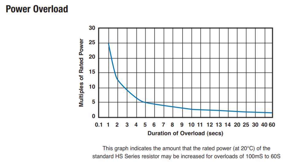
Most of the energy dissipation occurs within in the time-constant (), and longer means less pulse energy dissipation in the precharge resistor. Choosing a resistor that is continuously-rated for the peak power dissipation is unnecessary - most manufacturers will provide a power-overload factor, which is a guideline on how much the resistor can be overloaded, and for how long.
Consider the HS25 series resistor, which is a 25W rated power resistor. The graph below is extracted from the datasheet and shows the Power Overload curve. Our example calculations expect peak dissipation 92W, or about 4x overload. An instantaneous overload of 4x is acceptable for at least 5 seconds. We also sanity-check that our max current of 92W is less than the 1s overload rating, which it is. Any overload less than a second is considered a Pulsed Energy, and has different means of calculating.
In short, a 2.2k HS25 series resistor is a good choice for our example system. The design can be made even more conservative by solving for a longer time-constant, and precharging for or . This is especially important for Accumulators at or near 600V.
Ceramic and metal film resistors are typically unsuitable for this application.
Detect: Precharge Complete
- EV.5.6.1 a The Tractive Battery Pack must contain a Precharge Circuit. The Precharge Circuit must be able to charge the Intermediate Circuit to minimum 90% of the Tractive System voltage before closing the second IR
- EV.5.6.2 a The end of precharge must be controlled by feedback by monitoring the voltage in the Intermediate Circuit
The threshold is 90% so let’s conservatively select .
There are two approaches to measuring the threshold:
- Ratiometric - measure both and , compute the ratio in firmware. Automatically tracks pack state-of-charge and cell degradation over time.
- Fixed threshold - set a single voltage threshold based on the nominal pack voltage. Simpler to implement, but will drift relative to true pack voltage as the accumulator ages or is at low state-of-charge. The author recommends ratiometric instead, and competition scrutineers may not look favourably on a fixed-threshold method.
Detect: Precharge Failure
Since we’re measuring the TS voltage, we are able to identify and handle faults rather than blindly waiting on a timer. A failed precharge can be identified by:
- No voltage rise: indicates open-circuit precharge path, or shorted load
- Precharge too fast: indicates load may be disconnected, or was not correctly discharged from last power-cycle.
- Precharge too slow: indicates the Discharge circuit may be stuck-ON. Precharging for an extended period may destroy precharge/discharge components due to prolonged power dissipation.
Failure Mode: No voltage rise
Consequences: Likely none. Possible root causes: Open circuit - IR, precharge relay, or connector disconnected.
The simplest solution is to set a maximum precharge time before throwing an error.
Failure Mode: Precharge too fast
Consequences: Likely none. Possible root causes: Open circuit - Tractive System is not capacitively loaded by the motor drives. Check IR, precharge connections.
The simplest solution is to set a minimum expected duration. If the TS measures 90% charge before this expected duration, something is wrong. Throw an error.
Failure Mode: Precharge too slow
Consequences: Destruction of precharge and or discharge resistors. Possible root cause(s): Discharge stuck ON - worn out or simply not connected. Relay not energised, connector disconnected.
If the discharge relay is under-specced or worn out, contacts may become stuck closed due to arcing. In this situation, the discharge resistor presents as a constant load during precharge - causing precharge voltage to rise slower than expected, and most importantly, meaning that precharge will never complete.
The figure below shows the current path for this failure mode. Note the IR+ has been omitted, since it is currently de-energised and does not contribute to the failure mode.

Removing the unnecessary components, we can see that a voltage divider is formed by and , which will cap the maximum voltage that the TS can ever be precharged to. If this failure mode is left unhandled, you may blow up your precharge- and/or discharge-resistor.
This figure shows the motor-driver internal bleeder resistor , which is usually quite weak- worth double checking the value of this, if known.

We were track testing our premier EV in 2019. A test-run had just completed with some spurious fault that caused the IRs to open. We performed checks and restarted the TS. Shortly after, smoke was coming out the accumulator vents - I knew by the dry, acrid smell that the source was one of the resistors. Even so, we dumped the contents of a Dry Chemical fire extinguisher into our accumulator, stepped back, and waited. The cleanup inside the accumulator was a real drag. Still, at competition that accumulator helped us place middle of the field with our first EV entry!
Where to Next?
Coming Soon Reference Designs